
ACP22
Material description
Material ID: ACP22
Material type: Aluminium composite panel with a core consisting of polyethylene (PE) with ethyl vinyl acetate (EVA) copolymer, a fire retardant, and an inorganic filler.
Polymer: Polyethylene and ethyl vinyl acetate copolymer (33%)
Additives (fire retardants, fillers or traces of inorganic elements): Magnesium Hydroxide (64%), Silicon (1%), Sodium (1%), Calcium (1%), traces of other elements (<1%)
Core thickness: 3.17mm
Thickness of single metal skin: 0.5mm
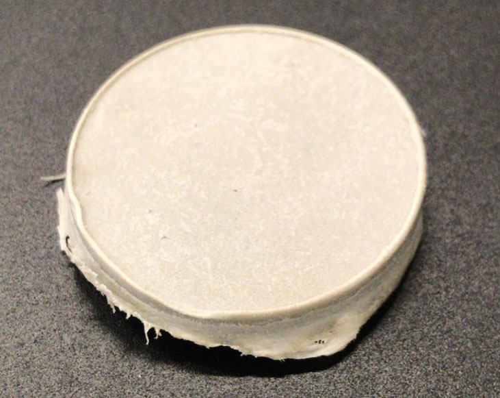
Table 1. Estimated mass concentration of compounds.
| Compound | Mass Concentration (%) |
|---|---|
| Polyethylene and ethyl vinyl acetate copolymer (-) | 33 |
| Magnesium Hydroxide (Mg(OH)2) | 64 |
| Silicon (Si) | 1 |
| Sodium (Na) | 1 |
| Calcium (Ca) | 1 |
| Traces of zinc (Zn) | <1 |
| Traces of iron (Fe) | <1 |
| Traces of potassium (K) | <1 |
| Traces of aluminium (Al) | <1 |
A. Material composition identification
A.1 Attenuated total reflection – Fourier transform infrared spectroscopy (ATR-FTIR)
Table 2. FTIR compound identification.| Identified Compounds |
|---|
| Polyethylene and ethyl vinyl acetate copolymer (-) |
| Magnesium Hydroxide (Mg(OH)2) |
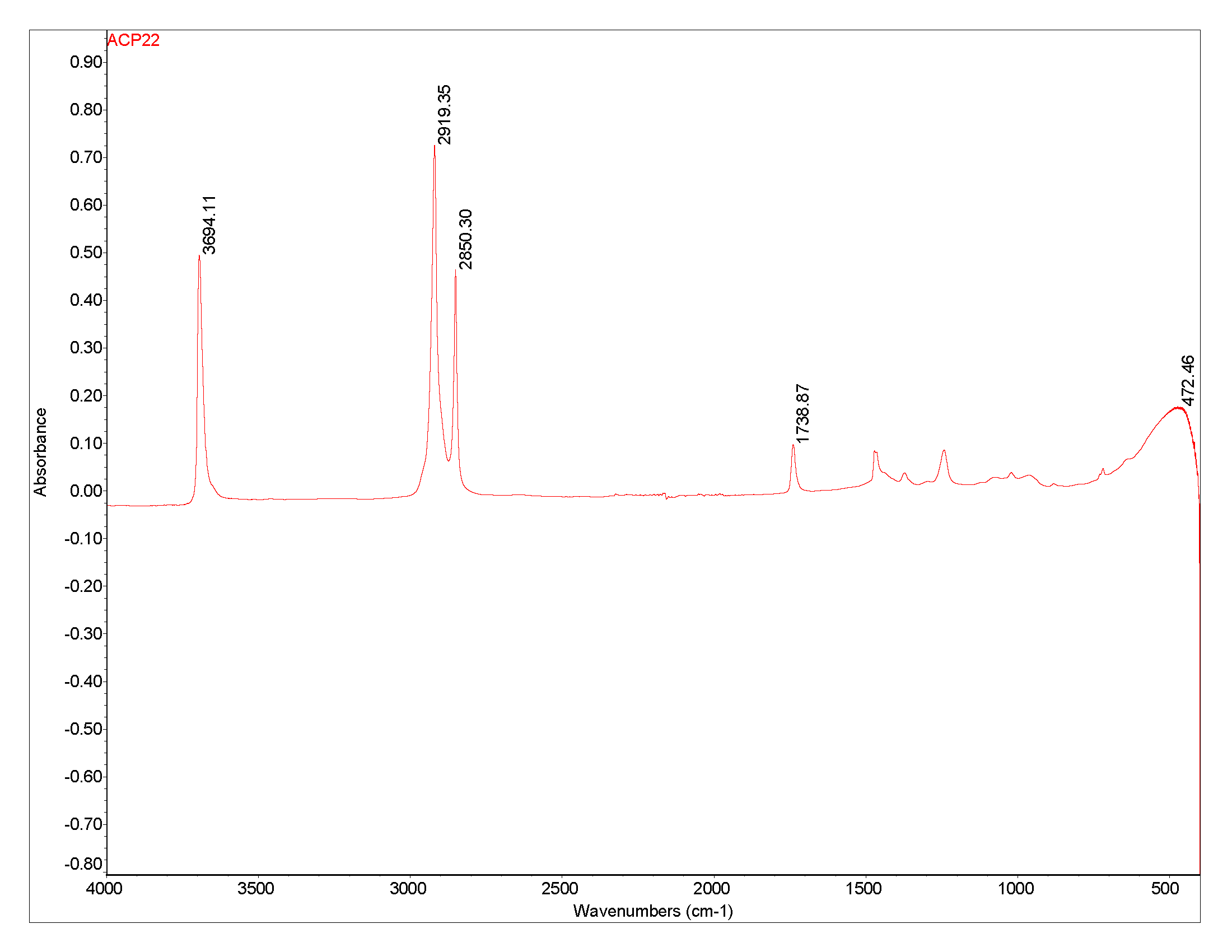
Figure 1 . FTIR spectra: Absorbance percentage versus wavenumber from the sample.
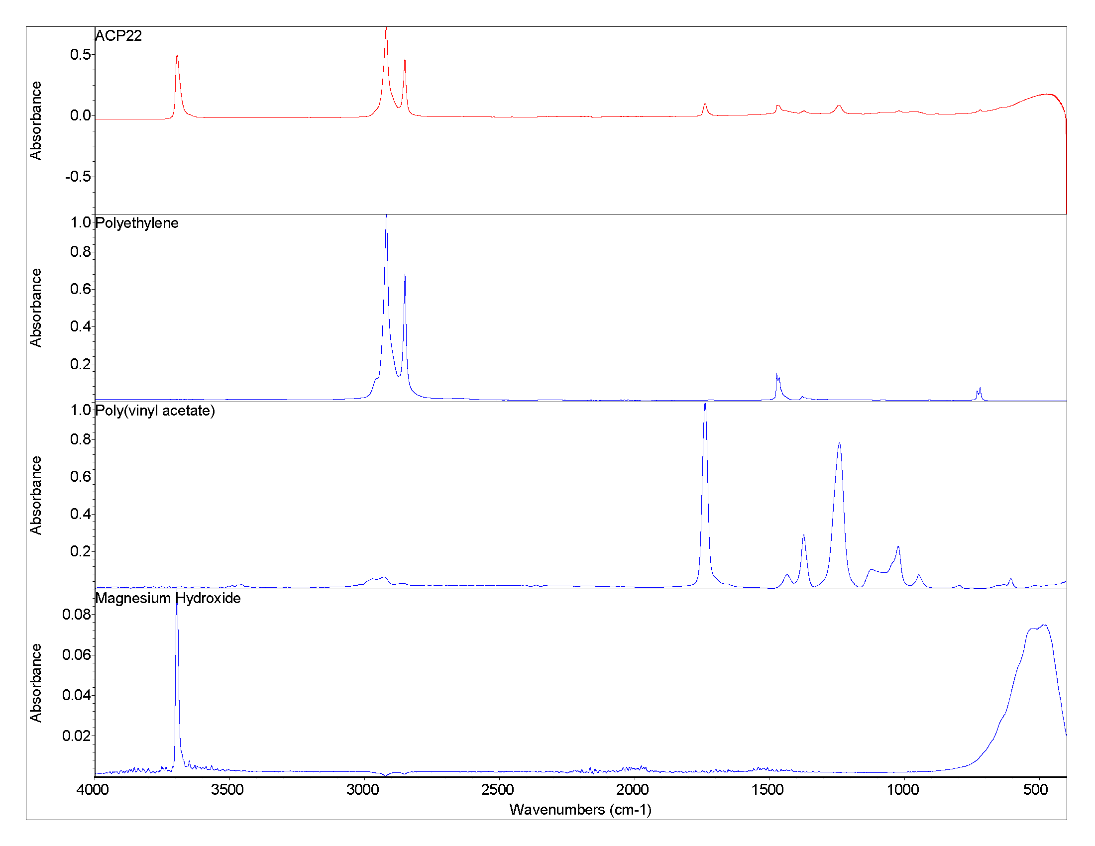
Figure 2. FTIR spectra: Absorbance percentage versus wavenumber from the sample and the identified compounds.
A.2 Energy Dispersive X-Ray Fluorescence (EDXRF)
Table 2. Inorganic elements and their mass concentration identified with EDXRF.
| Element | Mass Concentration (%) |
|---|---|
| Mg | 22 |
| Si | 1 |
| Ca | 1 |
| Zn | 1 |
| Fe | 1 |
| K | <1 |
| Al | <1 |
| K | <1 |
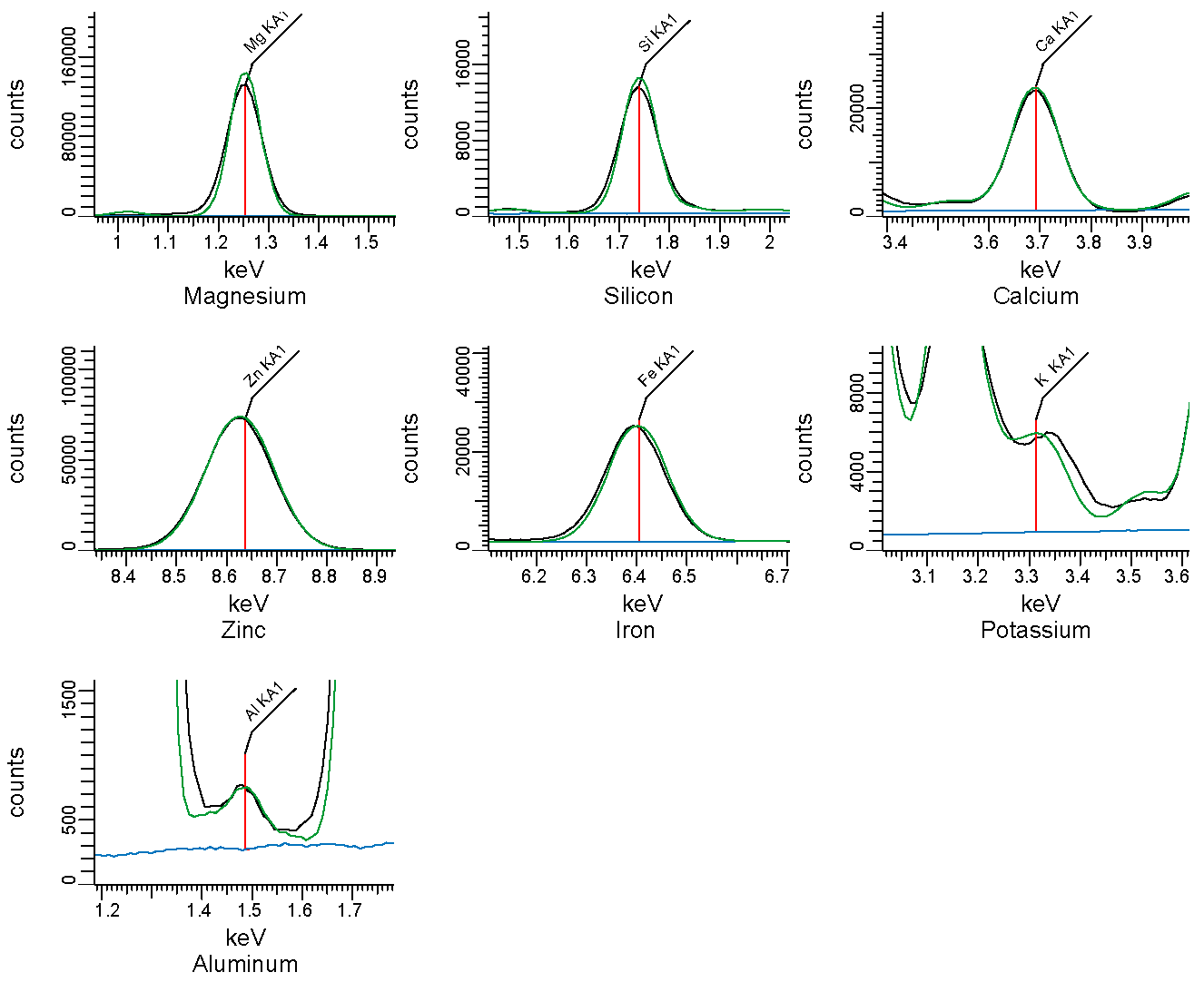
Figure 3. EDXRF spectra. Counts vs energy. Identified elements are shown as vertical lines.
B. Thermogravimetric analysis
Table 3. Mass fraction of residue after thermal decomposition.
| Condition | Fraction of mass residue at 800°C |
|---|---|
| Non-oxidative (nitrogen) | 0.43 |
| Oxidative (air) | 0.44 |
Table 4. Temperature and amplitude of main peaks in non-oxidative conditions.
| Peak ID | Temperature peak (°C) | Amplitude of peak (°C-1) |
|---|---|---|
| Peak 1 | 360 | 3.68 x 10⁻³ |
| Peak 2 | 482 | 8.24 x 10⁻³ |
| Peak 3 | 675 | 2.4 x 10⁻⁴ |
Table 5. Temperature and amplitude of main peaks in oxidative conditions.
| Peak ID | Temperature peak (°C) | Amplitude of peak (°C-1) |
|---|---|---|
| Peak 1 | 364 | 3.5 x 10⁻³ |
| Peak 2 | 472 | 7.7 x 10⁻³ |
| Peak 3 | 669 | 2.4 x 10⁻⁴ |

Figure 4. Normalised mass (solid line) and derivative of the normalised mass (dashed line) in 150 ml min-1 of nitrogen and a heating rate of 20°C min-1.
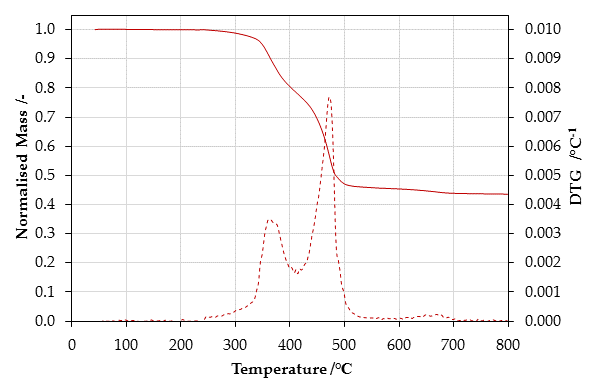
Figure 5. Normalised mass (solid line) and derivative of the normalised mass (dashed line) in 150 ml min-1 of air and a heating rate of 20°C min-1 .
C. Gross Heat of Combustion
Table 7. Gross Heat of Combustion individual results for sample.| Trial | ΔHc [kJ g-1] |
|---|---|
| Trial 1 | 15.93 |
| Trial 2 | 15.99 |
| Trial 3 | 15.88 |
| Average | 15.93 |
| Std dev | 0.06 |
D. Ignition parameters
Table 8. Summary of ignition parameters for sample.| Critical heat flux for ignition | Ignition temperature | Total heat transfer coefficient of losses | Apparent thermal inertia |
|---|---|---|---|
| q̇″cr [kW m−2] | Tig [°C] | hr [W m-2 K-1] | kρc [kW2 m-4 K-2 s] |
| 15 | 371 | 38.50 | 1.878 |
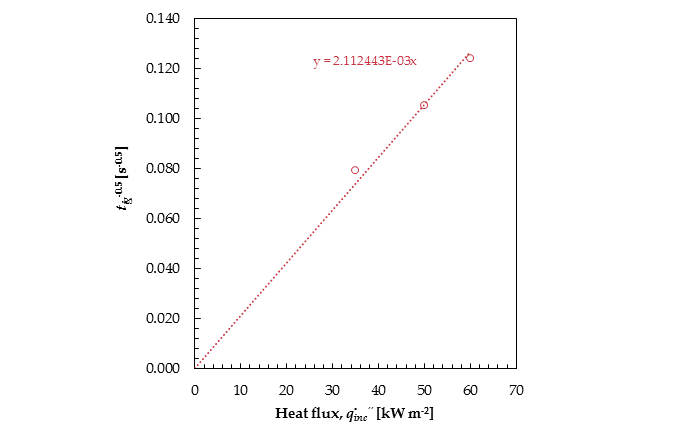
Figure 6. Time-to-ignition vs incident radiant heat flux for samples.
E. Burning behaviour
Table 9. Summary of key burning behaviour metrics.
| Heat flux | Test | Time to ignition | Fraction of mass residue | Peak heat release rate | Total energy released |
|---|---|---|---|---|---|
| q̇″inc [kW m-2] | tig [s] | mres [-] | q̇″p [kW m-2] | Qt [MJ m-2] | |
| 35 kW m-2 | |||||
| Test 1 | 166 | 0.46 | 120.49 | 72.57 | |
| Test 2 | 152 | 0.44 | 110.13 | 72.03 | |
| Avg | 159 | 0.45 | 115.31 | 72.30 | |
| 50 kW m-2 | |||||
| Test 1 | 87 | 0.46 | 141.76 | 78.99 | |
| Test 2 | 94 | 0.46 | 131.68 | 82.73 | |
| Avg | 90 | 0.46 | 136.72 | 80.86 | |
| 60 kW m-2 | |||||
| Test 1 | 65 | 0.43 | 161.55 | 75.53 | |
| Test 2 | 65 | 0.42 | 183.91 | 75.51 | |
| Avg | 65 | 0.42 | 172.73 | 75.52 | |
| 80 kW m-2 | |||||
| Test 1 | - | - | - | - | |
| Test 2 | - | - | - | - | |
| Avg | - | - | - | - |
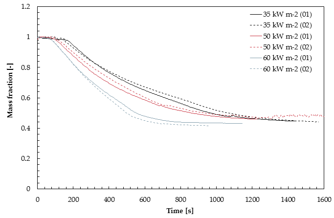
Figure 7. Normalised mass loss over time for samples tested with 35, 50, 60 and 80 kW m-2.
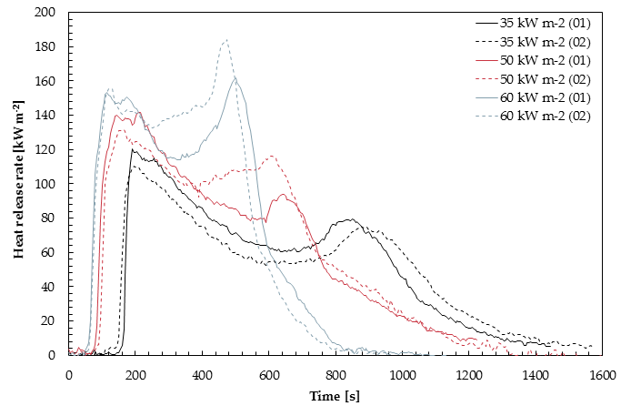
Figure 8. Heat release rate per unit area over time for samples tested with 35, 50, 60 and 80 kW m-2.
| Test | ΔHc [kJ g-1] |
|---|---|
| 35 kW m-2 (Test 1) | 30.18 |
| 35 kW m-2 (Test 2) | 28.33 |
| 50 kW m-2 (Test 1) | 29.09 |
| 50 kW m-2 (Test 2) | 29.85 |
| 60 kW m-2 (Test 1) | 29.61 |
| 60 kW m-2 (Test 2) | 28.82 |
| 80 kW m-2 (Test 1) | - |
| 80 kW m-2 (Test 2) | - |
| Average | 29.31 |
| Std dev | 0.69 |
F. Flame Spread
Table 11. Minimum heat flux for flame spread rate and minimum flame spread rate for sample.| Orientation | q̇″min.spread [kW m-2] | Vf.min [mm s-1] |
|---|---|---|
| Horizontal | 13.30 | - |
| Vertical | 9.90 | - |
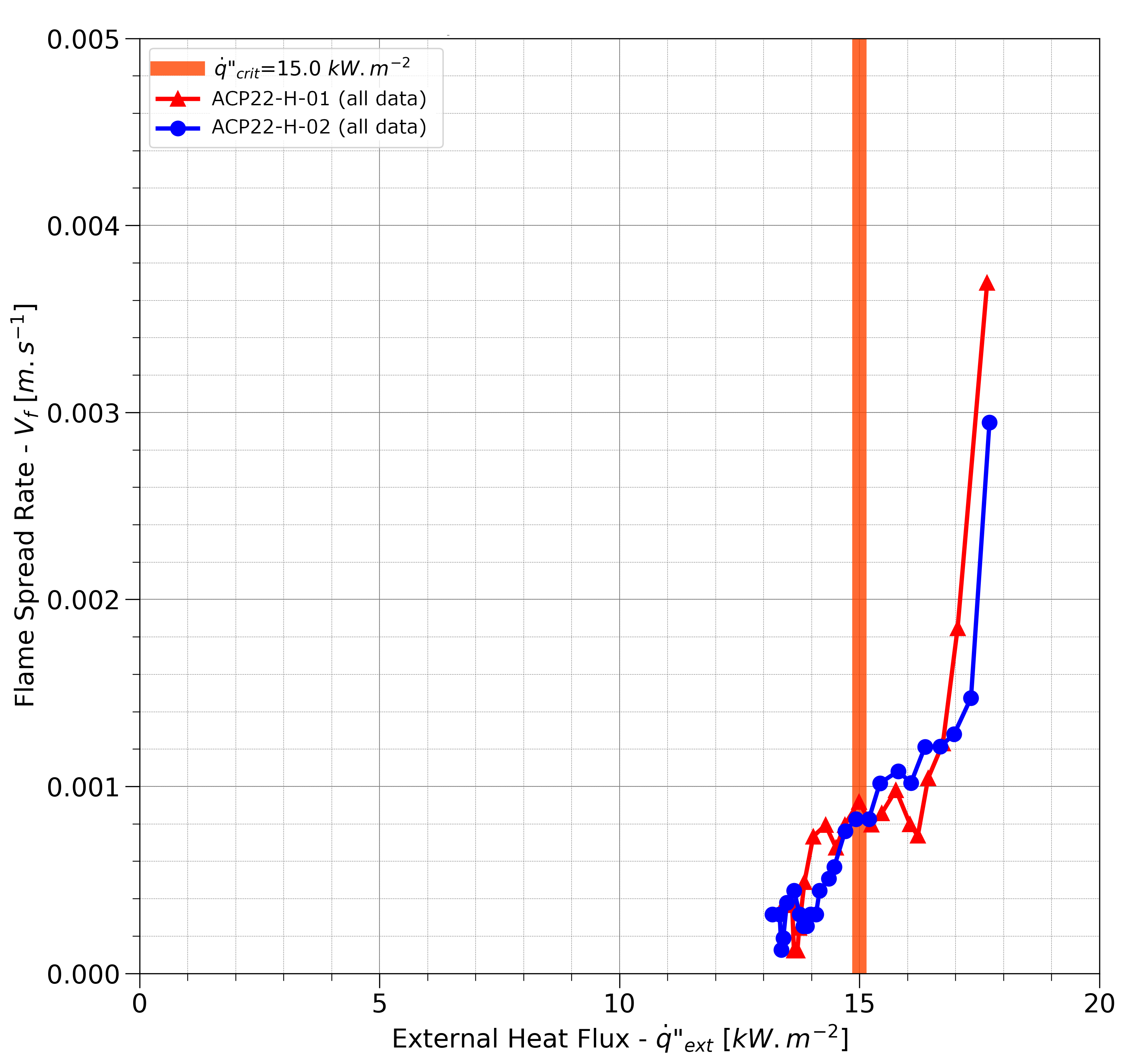
Figure 9. Lateral flame spread rate versus heat flux.
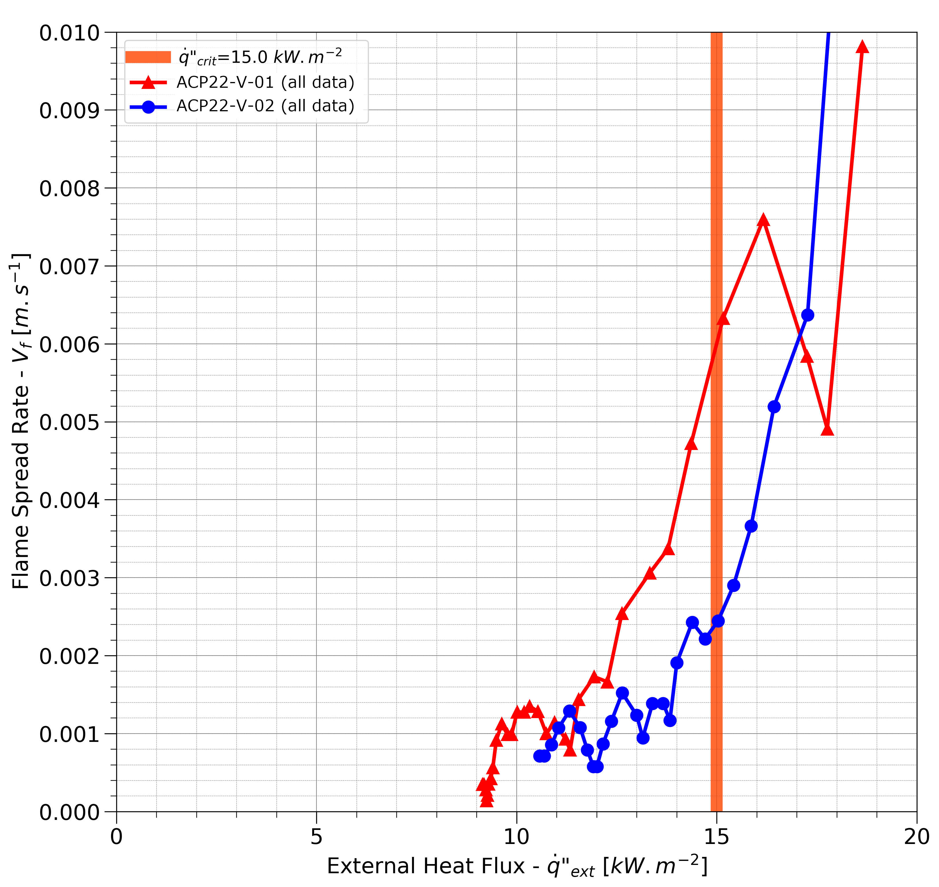
Figure 10. Vertical flame spread rate versus heat flux.

Figure 11. Vf-1/2 as function of q̇″ext in horizontal configuration.
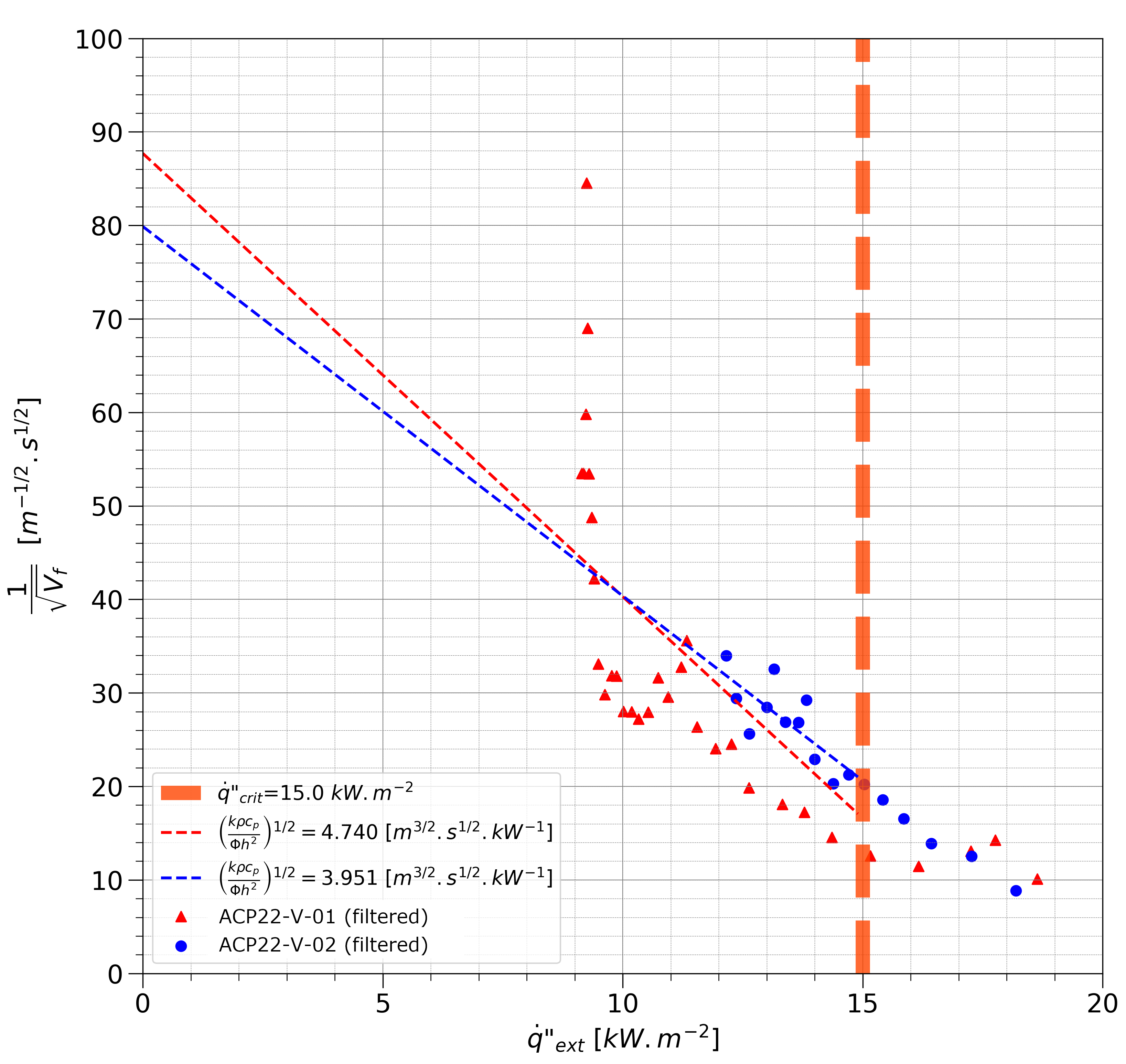
Figure 12. Vf-1/2 as function of q̇″ext in vertical configuration.
Table 12. Flame spread parameter results for sample.
| Orientation | Trial | (kρcp⁄Φh2)1⁄2 [m3⁄2 s1⁄2 kW-1] | Φ [kW2 m-3] |
|---|---|---|---|
| Horizontal | 1 | 19.864 | 3.21 |
| Horizontal | 2 | 13.823 | 6.63 |
| Vertical | 1 | 4.47 | 56.38 |
| Vertical | 2 | 3.951 | 81.15 |